Knock open your door. Keyless entry is just a knock away! Click the picture of the hand above
Very popular for escape rooms, safe rooms, secret rooms and cabinets!
This animation shows the interaction between the Knock Lock and the user. The "combination" for this illustration is "5 - 2 - 4" where the hand knocks five times then two and finally four. This illustrates a 3-DIGIT code. The code is USER SETTABLE and can be set from a 1-DIGIT code to a SIX-DIGIT code. Each DIGIT can be from 1 KNOCK to 63 KNOCKS!
The KnockLock is a secret knock detecting door device that is simple to use and capable of "sensing" a special and unique pattern of knocks. Actually a more appropriate name might be the
KnockUnlock since you use it to unlock.
The knocklock easily interfaces to "unlocking" devices such as
Electric door strikes, Door actuators, alarm disable, hidden switch applications, covert entry or the ultimate secret Electric Garage Door
opener allowing you to unlock or open the door simply by knocking a "special" way.
This is done by using a vibration sensor that senses "knocking" on or near the item or area and sends the "knocking" information to a processor
that is capable of recognizing a SPECIFIC and UNIQUE pattern. Once the "unique knocking" is sensed (for example:
KNOCK-KNOCK-KNOCK (pause) KNOCK-KNOCK (pause) KNOCK) the KnockLock then activates an internal relay that can switch power to a
lock mechanism (such as an electric door strike, electric car door lock or electric garage door opener for example). The "knocking" pattern that
is required to activate the KnockLock can be as simple as one knock or as complicated as six different groups of knocks, where each group
can be from one knock to 63 knocks (resulting in over 1 billion possible combinations). The combination must match EXACTLY before access
is granted and is completely programmable by the user.
The internal relay is rated at 2 Amperes at 30 volts DC.

The Pickup
Great Features!
The KnockLock will hold TWO different combinations with each being from one knock to six groups of knocks. The KnockLock has a built-in
PICK-UP element so the unit can be attached directly to a door or wall. For installations requiring the KnockLock to be mounted away from the
"knock area" an external pick-up element is provided which simply plugs into the "external input" jack on the KnockLock.
Dual power Input
The KnockLock can run from four AA batteries or an external power source from 9 - 15 volts DC or BOTH (i.e. Batteries could be used in
conjunction with external power for "combination" retention in the event that power was disrupted to the external power source)
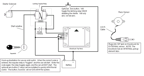
Accessory Ignition Input Terminal
Used to keep the KnockLock from resetting until this input goes negative for a period of 20 seconds. This is useful in an automotive kill-switch
application, so the user does not have to keep re-entering the code when the car is shut off briefly, and then re-started. Once the car has been
off for a period of approximately 20 seconds, the KnockLock will then reset.
Sensitivity adjustment for how "hard" of a knock is required to trigger the KnockLock.
10-Try Lockout. If ten incorrect attempts are made at entering the code, the KnockLock will lock-up for 15 seconds.
Programming
The KnockLock combinations can be set before OR after mounting. It is recommended that you familiarize yourself with the operation of the unit
before putting it into service.
To program COMBINATION #1:
STEP #1
Insert paper clip or toothpick into CODE hole (Fig. 3), pressing and holding the internal push-button through the entire programming process.
You will hear three tones indicating that you are in "CHANGE-CODE" mode.
STEP #2
While continuing to hold in the toothpick/paper clip, tap the KnockLock the number of times you want the FIRST digit to be. After the last tap, the
KnockLock will then verify what you tapped in by responding with a short "BEEP" for EACH tap. For example, if you want the first digit to be
FIVE, tap the KnockLock five times. When you stop tapping, the knock-lock would then "BEEP" five times. The first number is now entered.
STEP #3
Repeat STEP #2 by tapping in the SECOND digit for the code. Once again, the KnockLock will verify what you tapped in by "BEEPING" back
the number of taps. This process can be repeated for UP TO SIX digits.
STEP #4
When the LAST digit is "tapped" in, release the toothpick/paper clip from the program-hole, and the KnockLock will signal with two quick beeps
that it is ready for normal operation. The code setting is complete.
To program COMBINATION #2:
NOTE: The first digit of COMBINATION #2 MUST BE DIFFERENT than the first digit of COMBINATION #1. Other wise, COMBINATION #2 will
be disabled.
Step #1
Just as in setting the first combination, you must insert a toothpick/paper clip into the programming hole. You will then hear 3 tones indicating the
KnockLock is in "CHANGE-CODE" mode. BRIEFLY remove toothpick/paper clip, and then RE-INSERT toothpick/paper clip and you will hear
six quick tones indicating that it is ready to set COMBINATION #2. Continue to hold in the toothpick/paper clip through the entire programming of
COMBINATION #2.
Step #2
Follow steps 2 through steps 4 in "CHANGE-CODE" example above. When finished, remove toothpick/paper clip from CODE hole.
Mounting
The KnockLock should be securely mounted on a surface capable of conducting sound (such as wood, metal or plastic for example). Poor
mounting will result in poor sensitivity to the knocking. If the external sensor is being used, plug the 1/8" connector into the "REMOTE" hole (Fig.
1) and make sure it is mounted securely to the knock surface as well. The sensitivity control (Fig. 3) can be adjusted to fit the mounting
environment. This is done by turning the sensitivity control left or right with your thumb. On surfaces that are more "resonating" or surfaces that
lend themselves to reverberation, the sensitivity may have to be decreased to reduce false "additional" sound pulses. Experiment to find the
ideal sensitivity setting.
Normal Operation
When batteries are installed, the KnockLock will emit five short beeps. Pay close attention to the speed of these "beeps" as they occur at the
recommended "knock" rate for operation. During normal operation, the KnockLock is always listening for knocks. The rate at which the knocks
should occur is approximately 5 to 6 knocks per second. The knocks can be as fast as 12 times per second, or as slow as 4 times per
second. For our example, we will assume the code to be: 5 - 3 - 1 - 4
Knock five times and wait for the response BEEP. Immediately after the BEEP, knock three times and wait for response BEEP. Immediately
after that BEEP, knock one time and wait for response BEEP. Immediately after that beep, knock four times and STOP.
Note: If too much time goes by after a response BEEP, the KnockLock assumes you are done knocking. You have up to one second MAX to
knock the next number after a response beep.
If the procedure was done correctly , the KnockLock will play 9 tones very quickly, and engage the internal relay, activating the lock mechanism it
is connected to. If the KnockLock did not recognize the code, it will respond with four tones, reset and wait for another attempt.
Hint: Additional digits can be added in FRONT of the combination, and so long as the sequence ENDS with the correct combination, the
KnockLock will still activate. For example, if the combination is
5 - 3 - 1 - 4, the user can "knock in" 3-1-2-4-2-4-10-1-2 - 5-3-1-4 and the lock would still engage. This is useful if someone is standing nearby,
and you do not want them to easily figure out what you are doing, or to make the code seem much more complex than it really is.
When the correct combination is entered, the KnockLock’s normally-open relay contacts engage for a period of 2 seconds by default.
Battery Life
4 AA Alkaline batteries should last well over 1 year under normal usage. Some of our tests indicate that the batteries could last at long as 3 - 5
years. Make sure the sensitivity control is set so that the environment does not trigger the pick-up element, causing unnecessary power
consumption. When the batteries start to get low, the KnockLock will play an unusual sounding set of tones after each access attempt. Once
you hear this sound, you should replace the batteries within 1 month.
Wiring
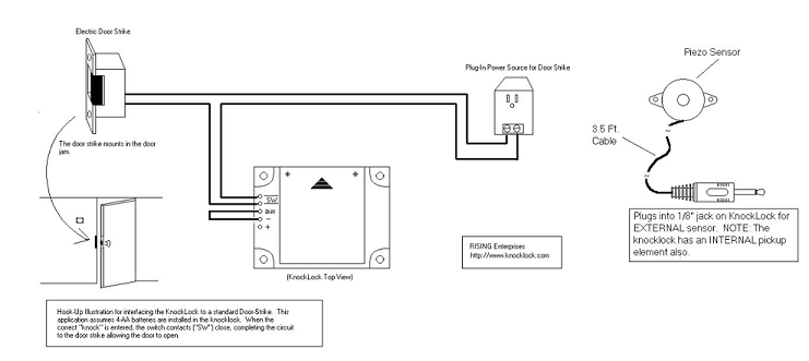
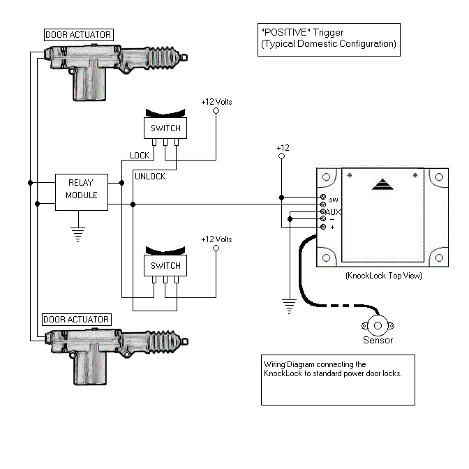
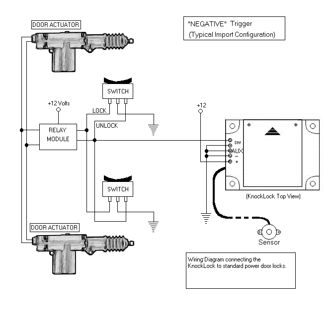
The KnockLock has five screw-wire terminals. Terminals 1 and 2 are the normally-open switch contacts that close when the correct combination
is entered. Terminal 3 is an auxiliary input for automotive applications. Terminal 4 is the NEGATIVE connection for an external power source
and terminal 5 is the POSITIVE connection for an external power source (from 9 to 15 VDC). To attach a wire to these terminals, simply loosen
the screw with a small screwdriver, insert the wire in the terminal hole and then tighten the screw down on the wire.
For the application of connecting to a garage door opener, simply parallel the two switch contacts of the wall mounted garage door opener
switch with the switch terminals on the KnockLock. The KnockLock would then simulate the garage door switch being pressed when the correct
combination is entered into the KnockLock.
The KnockLock’s relay switch contacts are rated at 2 Amps/ 30 VDC maximum. If higher current requirements are needed, the KnockLock’s
relay can be used to drive the coil of a heavy-duty relay, which would switch a much heavier current load.
Modify relay contact time
The "contact period" can be extended by pressing the "CODE" button when FIRST installing the batteries. After the five short start up beeps,
you will hear a lower pitch beep, approximately once per second. Each beep represents an extra SECOND of "contact" time. Release the
"CODE" button when the desired "contact period" has elapsed.
Great for secret rooms, safe rooms, escape rooms, cabinets or bookcases. Just knock to unlock!
 Please note
: that this item has just one output for a fail secure type of device such as an electric strike. If using it with a fail safe type of device such as a magnetic lock then an additional relay will be needed. See the relay module Item: 1389-C below.
 Size
Size: 3 3/4" X 3 1/8" (9.6cm X 7.8cm )

Typical electric strike door installation as can be used for access control or an escape room for example

Typical domestic car power Door Locks "Positive Trigger"

Typical import car power Door Locks "Negative Trigger"

Typical car kill switch
 Helpful Knocklock resources
Related Products
See our electric strike section - Use Knocklock with electric strikes and not mag locks! (unless an additional relay is used)
For cabinets see our electronic cabinet lock which works well with the KnockLock
Helpful Knocklock resources
Related Products
See our electric strike section - Use Knocklock with electric strikes and not mag locks! (unless an additional relay is used)
For cabinets see our electronic cabinet lock which works well with the KnockLockDon't forget the power supply!
Click here for power supply with battery back-up
